The ATX bench power supply. There are 3 red ports for 12v, 5v and 3v rails. The black port is ground.
This is a good place to start a blog.
Tired of using wall wall wart supplies for any electronics projects, I decided I need a real bench power supply. At the same time, I had an unused ATX power supply, and a sweet toggle switch looking for a good project. There are already a variety of ATX to bench supply conversion projects, ranging from very simple, to moderately complex. I wasn’t thinking about blogging at the time, and didn’t feel like dismantling the whole thing. So there’s not a lot of pictures of the construction. No two of these ATX bench supplies are the same, so it wouldn’t have helped much anyway. This post isn’t a how-to, it’s showing just of one variations of the ATX bench power supply.
This design is definitely on the simple end of the spectrum. It has two features that set it apart from most of the designs: A sweet missile launch switch, and the ATX connector on the PSU isn’t damaged. This 500W Antec looks pretty decent, so I didn’t want to destroy the possibility of ever using it in a computer. Instead of hacking the original supply to pieces, this has a small control box bolted to the top of the supply. The standard ATX cord that would normally connect to the motherboard is instead connected to the back of the control box. The only real modification to the PSU was drilling two small holes in the top, to connect the control box.
The red LED is standby. The Blue LED turns on when the 12v, 5v and 3v supplies are ready.

Rear view of the ATX plug.
Design
Parts list:
- Antec SP-500 500 watt power supply
- Sweet toggle switch
- Blue LED
- binding posts
- ATX connector
- 22 gauge stranded wire
- 2”x3”x1.5” aluminium enclosure, with 2 screws
- Two nuts and bolts
Some PSUs need a dummy load on the 12V rail. This Antec doesn’t, so the binding post circuits are straightforward, and a diagram isn’t needed. One 12v, 5v, 3V and ground pin from the ATX connector goes to the respective binding posts. In theory, the multiple 12v rails could be combined for higher amperage, but that would be overkill for what I need. Also, I might need a lower gauge wire for that.

Toggle Switch circuit
The LED toggle switch circuit is a little counter-intuitive and a diagram is helpful. Your computer power supply is usually left “on” with that small black toggle switch in the back. But it’s only once the motherboard demands power, that the PSU energizes its 12, 5 and 3 volt rails. It’s the PWR_ON pin on the ATX connector that signals the PSU to turn fully on. So there’s two toggle switches for power. When the main, back toggle switch is in the on position, the LED in the toggle switch turns on. That’s the sign it’s “armed.” This is the counter-intuitive part. The LED gets power from the PWR_ON pin on the ATX connector. The PWR_on pin is high, and the LED/resistor in the switch doesn’t tie it low. However, when the switch is flipped, the red LED is shorted, and the PWR_on pin is tied low. Once the PSU’s power is stable, the PWR_good pin is high, lighting up the soothing blue LED.
Putting it together
I put holes in the aluminum enclosure for the ATX female connector, the toggle switch, the LED, and the binding posts. There were two holes added to the bottom for securing it to the top of the PSU. Securing the box to the top was the only time you’re at risk for a big shock, since it involves opening up the ATX case, and drilling holes in the top to match up with the holes in the control box.

Inside the control box
Once the box was finished and secured, I soldered short sections of wire to the relevant pins on the female ATX connector: Ground, 12V, 5V, 3V, PWR_ON, and PWR_GOOD. With the wires in place, I added the switch, LED and binding posts to the enclosure (these have nuts and washers to secure it to the case). I finished the wiring everything and, lacking shrink tubes, insulated the wires with electrical tape. After a few test runs, the last thing to do was hot glue the ATX conector to case. It’s a snug connector, and takes some force to connect or disconnect. Hot glue works miracles.
Testing With Electrolysis

Before electrolysis
According to the sticker on the side, the output of one 12V rail is 19 amps – a deent amount for an electrolysis setup. I had these pliers that I found outside, completely rusted shut. No amount of prying would open this piece of crap. The quick and dirty process to clean electrolytically is:
fill some container with water, and saturate it with baking soda.
Connect the tool to be cleaned to some wire. This will connect to the anode. You want the metal reduced, adding electrons, so it’s connected to the ground.

During electrolysis
Then, some sort of sacrificial metal is needed. For this, I used some old aluminum foil. Make sure the aligator clip doesn’t get submerged with the aluminum, or else the clip will get corroded as well.
That’s all there is to it. I flipped the switch, and in an hour most of the work was done. I pried it open, sanded some to expose new metal. Opening still took quite a bit of force. I did this a couple more times over the course of an hour. As you can see, it took care of all the rust on the pliers. However, it was so badly corroded from before that it’s pitted.
This winter, I just might have to check its capabilities of charging a car battery. Hopefully not, though.

After electrolysis

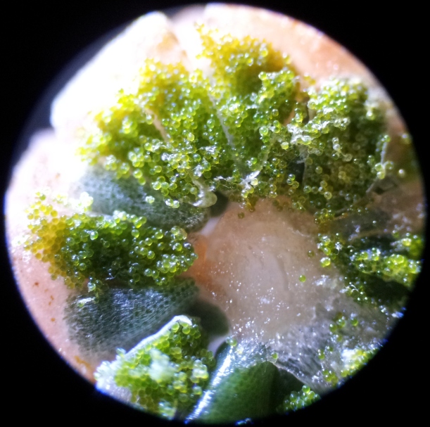
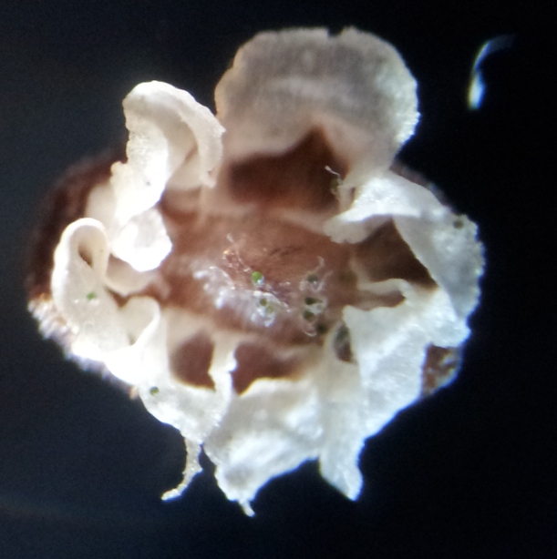
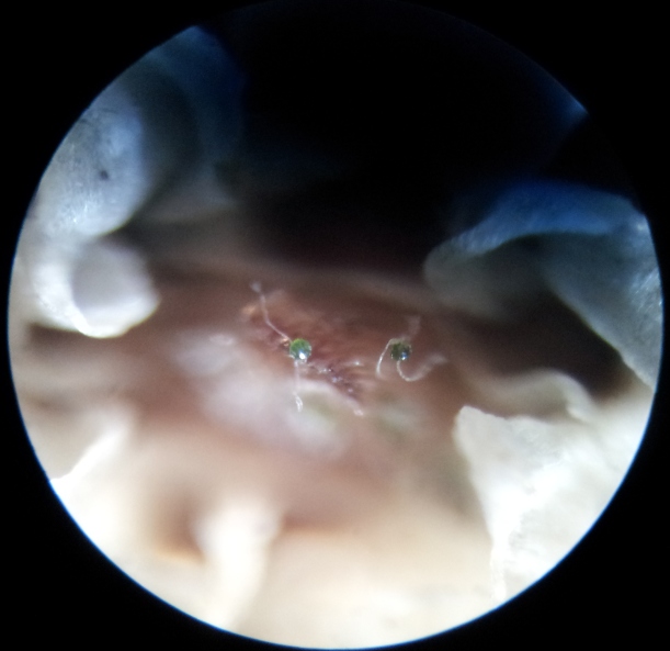
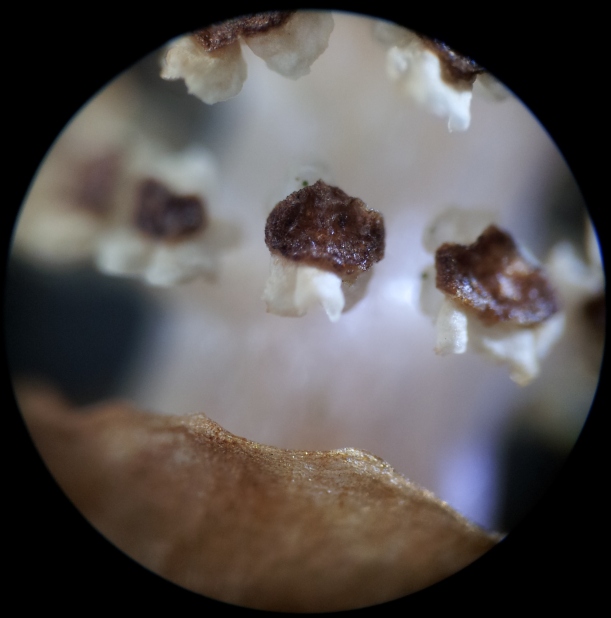
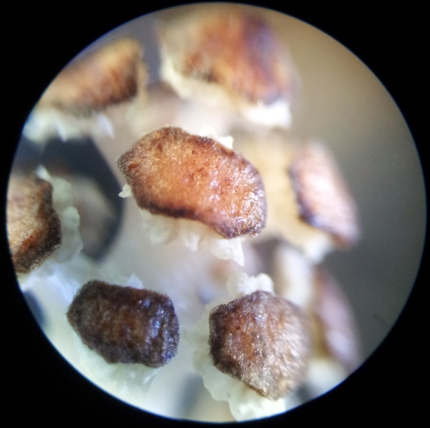
 This is my first post in a couple years, and I’ve been sitting on these pictures for a while. The picture above is a Horsetail. Although it looks like a mushroom, this is actually a plant. I don’t know which species it is, but Horsetails all belong to the genus Equisetum.